Raspberry Pi A+ Nixie NTP Clock
Who doesn’t like a Nixie tube based clock. Even my wife loved it. Bonus points if it’s very accurate.

I had in my parts box, for a very long time now, the display PCB from an old PH-meter. Old enough that it was done using Rusian 74141 clones - K155ID1 nixie drivers - a lot of logic chips (decade counters, serial latches, etc) and nixie tubes. It was also wired in a way that defied logic. Nobody could explain to me how it was supposed to work.
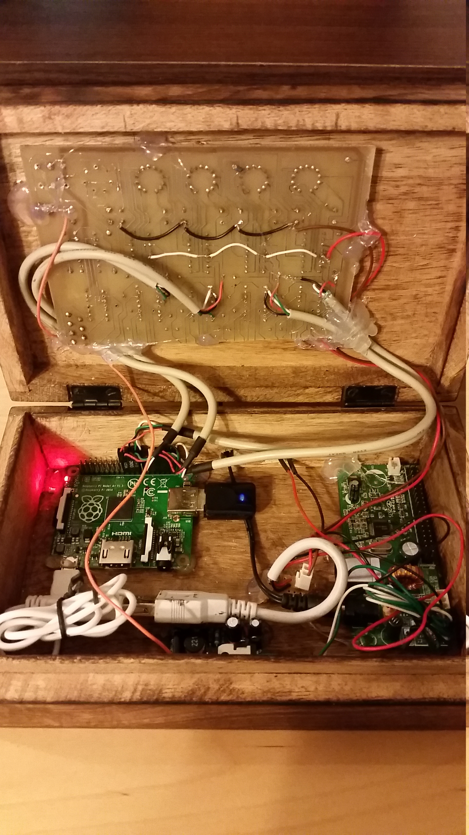
I used a hacksaw to discard everything from the old board except the nixie tubes and K155ID1 drivers.
A raspberry pi A+, a Nixie PSU from here [kosbo.com] and the PSU from an old IDE external HDD completes the build.
The A+ pi is nice because it’s cheap, small, draws less power than a B and has enough GPIOs to do away with any supplemental chips.
The first question I needed answered was if 3.3V is enough to drive the inputs of TTL chips (like the K155ID1). A breadboard circuit and a quick prayer not to burn the PI I had my answer: YES. Since I don’t read TTL outputs (feeding 5V to the unprotected PI GPIOs) I should be fine.
Second question, could I turn off a Nixie tube using the PI. Yes, setting the GPIOs driving the particular K155ID1 chip as inputs effectively turns off the tube attached to that driver.
The HV PSU takes 12V and outputs 150V for the tubes and 5V for the logic. Unfortunately the 5V part is done using a 7805 and so I was afraid a PI with a WI-FI adapter would be too much. I needed something outputting 12V and 5V with enough power for everything. I used the PSU (ok, the usb part is there too but unused) of a USB external 3.5 HDD enclosure.
The software part is quite easy. The PI has NTP configured to keep the clock accurate (and sets the time automatically on boot since the PI lacks an RTC). To drive the display part I run a simple python script.
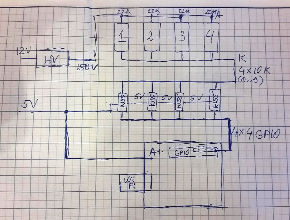
The schematic is pretty simple: 4 x 4GPIOs connect to A, B, C, D inputs of the four K115ID1 drivers, 0..9 outputs go to tube cathodes. 12V power the HV PSU that raises this voltage to 150V connected via 22K resistors to tube Anodes. The PI and the four drivers are powered by the 5V line.